learn more

Coordinate measuring machines with X-Y table

X-Y tables for small measuring ranges

The measuring microscope with X-Y table is the forefather of all coordinate measuring machines. The operator aims at the points of the object to be measured with an optical crosshair and, in the simplest case, reads the coordinates from the scales of the measuring table. Today, machines of this design are only used for the simplest measuring tasks. A major disadvantage is that the operator has a direct influence on the measurement result by visually moving to the measurement points. With measuring projectors, the function of the microscope is taken over by a projection screen with crosshairs. A comparison with transparent drawings can also be made on this screen.

Modern coordinate measuring machines with optoelectronic sensors are also often based on mechanically bearing X-Y tables (Fig. 38a). The z-axis is also mechanically bearing mounted. Today, most of these machines are fully automated in all three axes. The measuring range is approximately 200 mm to 400 mm. Significantly larger measuring ranges are not economical with this design.

<p>Fig. 38: Machine designs: a) X-Y table b) Guideways in a single plane c) Fixed bridge d) Moving bridge e) Computed tomography sensors f) Machine with horizontally arranged sensors and rotary table</p>

Guideway system determines the accuracy

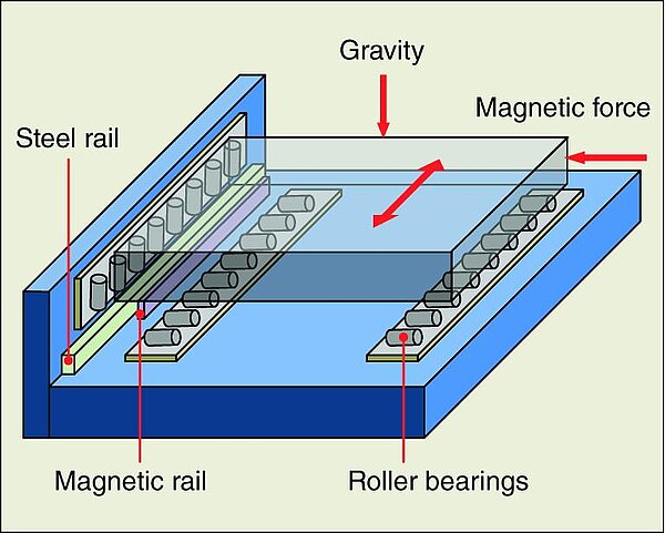
The X-Y table is realised in different accuracy classes. The use of simple, mechanically preloaded guideways (cross rollers, recirculating ball bearing principle) only allows medium accuracies. If, for example, higher demands are placed on the accuracy and long-term stability of the machines in the laboratory or in production monitoring, special design approaches must be taken. Aluminum is used as the system material to better control temperature influences. Its high thermal conductivity minimises temperature differences and thus deformation in the machines. In order to avoid expansion-related stress changes in the guideway systems, a special guide system is used in which the preload is generated by magnetic force and gravity (Fig. 39). This guideway system also significantly reduces friction and thus backlash. For this reason, friction-generating covers (bellows) are largely dispensed with.

Guideway system determines the accuracy
<p>Fig. 39: Tension-constant guideway system of the Werth measuring stages</p>

Long-term stable guideway system

The long-term stability of the system is also supported by the fact that the guideways are manufactured without adjustment. They are manufactured in a precision machining process with straightness errors of approx. 1 µm. In conjunction with temperature compensation, this design principle is ideal for applications with large temperature fluctuations.

Basic image processing equipment

The machine shown as an example in Figure 40 uses image processing sensors with Werth zoom optics as the basic sensor equipment, linking high flexibility with high accuracy. Powerful automatic transmitted and incident light illumination systems are integrated for this purpose.

Basic image processing equipment
<p>Fig. 40: VideoCheck® 400: compact multisensor coordinate measuring machine with tension-constant guideways</p>

Modular multi-sensor systems

The scanning-capable continuous path control allows the system to be equipped with a laser sensor (WLP), a three-dimensional measuring probe system or the Werth Fiber Probe®. This turns the machines into multisensor coordinate measuring machines. If required, rotary and tilt heads for the touch probes or rotary axes for the measuring objects extend the range of applications for this machine class.