learn more

For decades, the human eye was the only available "sensor" for optical coordinate measuring machines such as measuring microscopes and measuring projectors. Visual measurement leads to subjective measurement errors. These include parallax errors (oblique aiming) and incorrect measurements of light-dark transitions (e.g. at edges) due to the logarithmic light sensitivity of the human eye. Despite all the disadvantages, visual probing is the last possible alternative, even with modern machines. It is used when the object structures to be measured are very difficult to see and the geometric features can only be found intuitively.

<p>Fig. 6: Classification of sensors according to the physical principle</p>

Optoelectronics replaces the eye

Today, the tasks of the eye in measurement are performed by optoelectronic sensors. Like the eye in a measuring microscope, these act either perpendicular to the optical axis in the object plane (lateral sensors – image processing) or along the optical axis during focussing (axial sensors – distance sensors, Fig. 6). Lateral sensors determine the deviation of the object points from the sensor axis (sensor coordinates x, y in the object plane). For this purpose, the measuring object is usually illuminated and imaged onto the sensor using a lens (Fig. 7).

Point-shaped probing sensors from this group (e.g. Werth Tastauge) allow automated switching "probing" of edges and focussing with good contrast. They can therefore practically only be used in the transmitted light method. Due to this limitation, such sensors are hardly used any more. Today, image processing sensors that measure area are predominantly used, which can also analyse less high-contrast images. In special applications, measurements are also made using methods in which the width of an object (e.g. gap dimension or shaft diameter) is determined by analysing a laser light curtain.

Optoelectronics replaces the eye
<p>Fig. 7: Basic structure of a lateral measuring sensor with optical object imaging: a) sensor, b) lenses, c) measuring object, d) illumination</p>

Time of flight or angle measurement

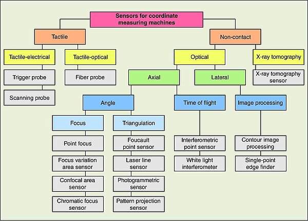
Only measurements of two-dimensional (2D) or stepped (2½D) objects can be carried out with lateral measuring sensors. In order to carry out three-dimensional (3D) measurements of workpieces with optical sensors, additional methods are required to measure along the third coordinate axis. As the sensors used for this purpose determine the distance between the sensor and the workpiece surface, they are also referred to as distance sensors or axial measuring sensors. These distance sensors work according to different physical principles, which can be roughly categorised into time-of-flight and angle-based methods (see Fig. 6). The time of flight of a light beam from the sensor to the object and back can currently not be determined directly for short distances, but only using interferometers. The angular relationships between the measurement beam and the sensor or between the aperture of the optics and the working distance are used in triangulation and focussing methods to determine the distance (Fig. 8).

The benefits of optical sensors for this application lie in the non-contact measurement. This means that both sensitive workpieces and those with small features can be measured. Plastic parts, optical functional surfaces, flexible sheet metal parts and components for micromechanics (implants, watches) are typical measuring objects. Non-contact measurement eliminates the need for difficult set-ups for small or elastic parts. With optical sensors, many measurement points can be captured very quickly or even simultaneously. Compared to other sensors, their use therefore usually leads to significantly shorter measuring times. For this reason, they are used for a wide variety of workpieces in production monitoring.

Time of flight or angle measurement
<p>Fig. 8: Distance measurement methods: a) Interferometer (time of flight): The distance to the object can be determined by interference from the transit time difference between the reference beam and the measurement beam. b) Triangulation (angle): The distance to the object can be determined from the position of the light spot in the measurement field and the known triangulation angle (sensor arrangement according to Scheimpflug to avoid blurring). c) Focus method (angle): The distance to the object is determined from the focus state, defocussing depends on the aperture angle</p>
Image processing sensors
Focus variation sensors
Laser triangulation sensors
Chromatic focus sensors
Interferometric point sensors
Confocal area sensors
Area sensors with pattern projection
White light interferometer