learn more

Image processing sensors

Highly accurate non-contact measurement in 2D

Image processing is part of the basic equipment of most optical and multisensor coordinate measuring machines due to its flexible application options and the good visualisation of the object and the measured features. Similar to image generation in visual measurement with measuring microscopes, the measuring object is imaged through a lens onto a matrix camera in the simplified manner shown in Figure 7. The camera electronics convert the optical signals into a digital image, which is used to calculate the measurement points in an evaluation computer with corresponding image processing software. The intensity distribution in the image is analysed. The individual components such as lighting systems, imaging optics, semiconductor camera, signal processing electronics and image processing algorithms have a decisive influence on the performance of image processing sensors[1, 4].

<p>Fig. 7: Basic structure of a lateral measuring sensor with optical object imaging: a) sensor, b) lenses, c) measuring object, d) illumination</p>

Telecentric lens for constant image scale

Imaging optics with a telecentric lens lead to the smallest measurement errors. Due to the telecentric lens, the image scale remains almost constant when the object distance changes within the telecentric range (Fig. 9). An aperture ensures that only almost parallel light rays are involved in the image generation for each pixel. This is particularly important for lenses with telecentric lenses for a constant image scale at low magnifications, as these have a large depth of field, which is why they can only be roughly focussed on the lens. Telecentric lenses with fixed magnification achieve the best quality.

Telecentric lens for constant image scale
<p>Fig. 9: With non-telecentric imaging (left), the sharpness and image size change with the object distance. With object-side telecentric imaging (right), however, the image size remains almost the same. a) sensor plane, b) virtual image plane, c) aperture</p>

Changing lenses: Selecting magnifications

It makes sense to combine high and low magnifications for the application. For example, less precisely toleranced features should be measured as quickly as possible in an image or still be found even if they are roughly positioned on the measuring machine. At the same time, there may be a requirement to measure narrow-tolerance features in small image fields highly accurately. Different magnifications can be set with a turret by changing the lenses. The disadvantage lies in the often insufficient reproducibility when changing lenses. Two or more lenses can also be combined by splitting the imaging beam. However, it may not be possible to measure dark measuring objects due to the loss of light during beam splitting. Since only two different magnifications are usually required, an elegant way is to switch between two fully-fledged image processing sensors with different magnifications mounted next to each other by positioning the precise machine axes that are already present. The magnification of common telecentric lenses ranges from 0.1 to 100 with field of view sizes of approx. 100 mm to 0.1 mm.

Zoom: Setting magnifications

Zoom optics offer the greatest flexibility. In conventional zoom optics, the movement of the lens packages is realised by mechanical curved guides (Fig. 10a). The positioning movements of the optical components in the lenses cause losses in accuracy, but these can be reduced by taking suitable measures. The simplest but very time-consuming method consists of repeated qualification after each zooming process. In order to achieve high reproducibility when zooming, motorised linear guides with minimal positioning uncertainty are used (Fig. 10b). The mechanical curved guides are replaced by corresponding characteristic lines in the control software. This allows different working distances to be realised in addition to different magnifications. In practice, magnifications of 0.5 to 10 and working distances in a department of 30 mm to a maximum of 250 mm can be achieved.

Zoom: Setting magnifications
<p>Fig. 10: Werth Zoom with adjustable magnification and variable working distance compared to conventional zoom optics: a) Collision with rotationally symmetrical parts and deep bores b) Collision is avoided</p>

Werth Zoom: Setting the working distance and magnification

By selecting the appropriate magnification, the most favourable compromise between the measuring range of the sensor and the achievable measurement uncertainty can be selected. The working distance can be adapted to the requirements of the measuring object largely independently of this: accurate measurement with a calibration standard working distance with the best image quality or measurement with a large working distance to avoid collisions.

The illumination systems are the basis for every optical measurement and ensure that the features to be measured are displayed with the highest possible contrast. This is most easily achieved on the outer edges of the measuring objects. In this case, transmitted light can be used (Fig. 11a). Flat measuring objects offer ideal conditions. In contrast, with spatially extended edges (prismatic or cylindrical objects), the interaction between the illumination, measuring object and imaging beam path must be taken into greater consideration. The aperture angles (apertures) of the illumination systems and the lenses must be matched to each other, taking into account the application (shape of the measuring object).

Werth Zoom: Setting the working distance and magnification
<p>Fig. 11: Types of illumination: a) Transmitted light; b) Brightfield incident light integrated into the lens; c) MultiRing® darkfield incident light, height-adjustable for lenses with fixed working distance; d) MultiRing® darkfield incident light in combination with Werth Zoom: A1: flat incidence of light, short working distance; A5: steep incidence of light, long working distance</p>

Transmitted light aperture according to requirements

Aperture-adjustable transmitted light units offer maximum flexibility. Surface illumination sources can be realised using an aperture with a large number of small holes (Werth FlatLight, see Fig. 47 Coordinate measuring machines for two-dimensional measurements ) with a small aperture. In practical applications, it is rarely possible to measure all features with transmitted light. For this reason, incident light illumination systems are usually also used. There are two types: The brightfield incident light (Fig. 11b) is projected onto the measuring object parallel to the optical axis of the imaging beam path. Ideally, this is done directly through the lens systems of the imaging optics. This type of illumination causes a direct reflection on metal surfaces that are perpendicular to the imaging beam path, for example. The measuring object is displayed brightly. Inclined surfaces reflect the light past the lenses and are therefore imaged dark. The darkfield incident light shines onto the measuring object at an angle to the imaging beam path. The light is reflected into the lenses (light) or past them (dark) according to the angularity of the workpiece surface. The contrast on the object structures of interest can be optimised by selecting the type of illumination.

Flexible incident light for optimum contrast

In the simplest case, ring-shaped arrangements of light-emitting diodes (LEDs) are used for the darkfield incident light. By switching on different diode groups, the object can be illuminated from different spatial directions and thus optimally adapted to the measurement task (Fig. 11c). With MultiRing® illumination (Fig. 11d), in combination with zoom optics with a variable working distance (see Fig. 10, p. 16 Image processing sensors ), it is also possible to vary the angle to the optical axis over a wide department. In addition, measurements can be taken at a sufficiently large working distance from the objects. Figure 12 shows examples of the effects of different types of lighting. The light sources can be controlled by the operator or – in automatic mode – by the measurement software. In order to be able to measure in a practical manner, i.e. on changing material surfaces such as metal surfaces with different degrees of gloss and differently coloured plastic parts, light control is used. It automatically adjusts the lighting to the values specified by the programme based on the light reflected by the object. A mathematical correction of the lighting characteristics (light intensity in relation to the set value in the user interface) also allows the CNC programmes to be used with different lighting hardware with different lighting characteristics, e.g. on different machines or after repairs.

Flexible incident light for optimum contrast
<p>Fig. 12: Measuring object with different types of illumination: a-d) Darkfield incident light from different orientations; e, f) Brightfield and darkfield incident light on the same object; g, h) Improvement with low contrast (g) through flat illumination with MultiRing® (h)</p>

Resolution vs. speed

Today, the images of object sections are usually captured with semiconductor cameras. CMOS cameras now often achieve even better signal quality than CCD cameras. The cameras have approx. 700 to 5000 pixels (pixel: picture feature) per line with a pixel size of around 5 µm. Cameras with a high resolution (many pixels) can capture larger object areas, but are significantly slower than those with a lower resolution. A high frame rate is a benefit, for example, when measuring according to the focus variation method (see Focus variation sensors, p. 24 ff.) or in OnTheFly® operation (see Measuring during movement).

Cameras deliver digital signals

Signal processing electronics convert the pixel amplitudes into digital values. This mainly takes place in the camera itself. The signals are transmitted digitally to the computer via GigE or alternatively USB.

Filters improve the image

The image processing algorithms used to analyse the image content and determine the measurement points also have a significant influence on the quality of the measurement results from image processing sensors. Today, evaluation is mainly realised using PC hardware and software. In a first processing step, the image can be improved with image filters (optimising contrast, smoothing surface defects: Fig. 13a, b). In the simplest method for determining the measurement points, the intersections of predefined lines in the image with the visible contours of the object are determined, e.g. by threshold operations (colloquially known as Edge Finder). This is repeated one after the other at many points in a previously defined evaluation area (window). This results in a large number of measurement points, which are summarised into a group by the window. However, a separate one-dimensional evaluation is carried out for each individual point determination. The comprehensive two-dimensional information contained in the image is therefore not taken into account. This is particularly disadvantageous when measuring in incident light. Interfering contours caused by surface structures, chipping and soiling can only be recognised and compensated for to a limited extent.

Filters improve the image
<p>Fig. 13: Image processing methods: a) Original image: contour determination disturbed, b) Improvement by image filter: contour determination correct, c) Incorrect measurement due to soiling, d) Correct measurement including form error due to contour filter</p>

Contour image processing for reliable measurement

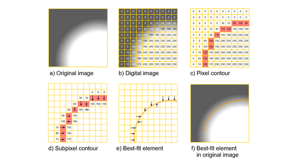
In contour image processing, the image within an evaluation window is viewed as a planar whole. Contours are extracted from this image using suitable mathematical algorithms (operators). Each pixel of a contour corresponds to a measurement point. The measurement points are strung together like a string of pearls. This makes it possible to recognise and filter out interferences during measurement (contour filters) without changing the form of the contours (Fig. 13c, d). It is important for practical use that several contours can be differentiated within a capture range (Fig. 14c, d). In a further step, modern systems interpolate the coordinates of the measurement points within the pixel grid (subpixeling: Fig. 15) and thus allow higher accuracies[5].

Contours larger than the field of view of the respective lenses can be captured as a whole using automatic contour tracking in conjunction with the CNC axes of the coordinate measuring machine (contour scanning). This scanning method is well suited to checking a small number of relatively large contours, e.g. on punching tools. In this application, both the punches and dies of the cutting tools are captured directly on the cutting edge and can be compared with each other or with the CAD data set.

Contour image processing for reliable measurement
<p>Fig. 14: Contour image processing compared to point-by-point evaluation: a, b) point-by-point evaluation: correct measurement with exact edge position (a), incorrect measurement if edges are displaced (b); c, d) contour image processing: contour selection in large window enables reliable location of edges in different positions. Fig. 15: From the original image to the calculated best-fit element: a) The image processing sensor "sees" the object as a grey image. b) The pixels of the grey image are converted into digital amplitudes. c) A pixel contour is calculated from the digital image using a threshold operator. d) A "sub-pixel point" is interpolated from the neighbouring values for each point of the pixel contour. e) A best-fit element is calculated from the sub-pixel contour, e.g. according to the Gaussian method. f) The result is displayed in the grey image for visual inspection</p>

Raster scanning: resolution independent of the measuring range

Another method for capturing larger areas of the workpiece is "Raster Scanning HD". Here, the image processing sensor captures images of the workpiece at high frequency during movement (Fig. 16). These are resampled and overlaid to create an overall image with up to 4000 megapixels (as of 2019). In the "in the image" evaluation, for example, 100 bores can be measured in 3 s (see Sensors and device axes). The accuracy is also increased by measuring large areas with high magnification and averaging over several images, which improves the signal-to-noise ratio. The method can be adapted to the requirements of the measurement task (see Measurement during movement).

Image processing is initially only suitable for the measurement of two-dimensional features. Accordingly, the field of application includes all two-dimensional measuring objects such as flat metal sheets, foils, printed circuit boards, cross sections of aluminum, rubber or plastic profiles, prints, inserts, lead frames and chrome masks. If focus methods are also realised with the same sensor hardware (optics, camera technology, etc.) (see focus variation sensors), the frequently used basic sensor type for multisensor coordinate measuring machines is available. By combining both methods in one sensor hardware, many three-dimensional measuring tasks can be solved. Determining the functional dimensions of plastic parts, such as the distance of latching lugs and the geometry of sealing grooves and connector latches, is one of the main areas of application. Other examples of applications include punched bent parts made of sheet metal, watch components, furniture fittings, nozzles for fuel injection, print heads, tools and turned parts.

A swivelling camera head can be used for flexible three-dimensional measurement with image processing sensors. The standard types of illumination described and an interchangeable interface for the fiber probe (see Measuring tactile-optical sensors) are integrated into this. A tilt and swivel head, which is also used for tactile sensors, allows the sensor to be spatially aligned with the workpiece. A further interface allows different optical or tactile sensors to be operated in automatic alternation (Fig. 17).

Raster scanning: resolution independent of the measuring range
<p>Fig. 16: Raster scanning HD: Many single images (yellow squares) are captured during the movement on a predetermined path (blue line) and merged into a high-resolution image (blue rectangle). All contours (red) in the measurement window (green) are captured automatically. Fig. 17: Swivelling sensor with image processing and fiber probe for measuring cooling holes on engine parts (small partial illustration)</p>

Raster scanning: resolution independent of the measuring range

Another method for capturing larger departments of the workpiece is "HD raster scanning". Here, the image processing sensor captures images of the workpiece at high frequency during movement (Fig. 16). These are resampled and overlaid to create an overall image with up to 4000 megapixels (as of 2019). In the "in the image" evaluation, for example, 100 bores can be measured in 3 s (see Sensors and device axes, p. 89 ff.). Measuring even large departments with high magnification and averaging over several images, which improves the signal-to-noise ratio, also increases accuracy. The method can be adapted to the requirements of the measuring task (see Measuring during movement, p. 95 f.).

Image processing is initially only suitable for measuring two-dimensional features. Accordingly, the field of application includes all two-dimensional measuring objects such as flat metal sheets, foils, printed circuit boards, cross sections of aluminum, rubber or plastic profiles, prints, inserts, lead frames and chrome masks. If focus methods are also realised with the same sensor hardware (optics, camera technology, etc.) (see focus variation sensors, p. 24 ff.), the frequently used basic sensor type for multisensor coordinate measuring machines is available. By combining both methods in one sensor hardware, many three-dimensional measuring tasks can be solved. Determining the functional dimensions of plastic parts, such as the distance of latching lugs and the geometry of sealing grooves and connector latches, is one of the main areas of application. Other examples of applications include punched bent parts made of sheet metal, watch components, furniture fittings, nozzles for fuel injection, print heads, tools and turned parts.

Raster scanning: resolution independent of the measuring range
<p>Fig. 16: Raster scanning HD: Many single images (yellow squares) are captured during the movement on a given path (blue line) and merged into a high-resolution image (blue rectangle). All contours (red) in the measurement window (green) are captured automatically.</p>

A swivelling camera head can be used for flexible three-dimensional measurement with image processing sensors. The standard types of illumination described and an interchangeable interface for the fibre probe (see Measuring tactile-optical sensors, p. 45 ff.) are integrated into this. A tilt and swivel head, as used for tactile sensors, allows the sensor to be spatially aligned with the workpiece. A further interface allows various optical or tactile sensors to be operated in automatic alternation (Fig. 17).

<p>Fig. 17: Swivelling sensor with image processing and fiber probe for measuring cooling holes on engine parts (small partial illustration)</p>