learn more

Confocal area sensors

Topography measurements in the submicrometre range

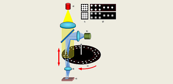
A confocal area sensor (e.g. Werth NFP: Nanofocus Probe, Fig. 24) projects light onto the object via an imaging system. A small pinhole diaphragm reduces the size of the light spot to a very small department. If the light spot is defocussed by moving the sensor head, the light is distributed over a larger area and the dimmed light spot on the object becomes darker.

Intensity curve determines the measurement points

An intensity curve is therefore created when the probe head is moved in relation to the object. This is recorded via a photosensitive sensor. The maximum of the intensity curve represents the location of the object surface. In order to be able to measure several points simultaneously with this principle, mutual interference between neighbouring points must be avoided during defocusing (Fig. 24f).

Intensity curve determines the measurement points
<p>Fig. 24: Confocal area sensor: a) Light source, b) Matrix camera, c) Rotating aperture (greatly simplified), d) Lens, e) Measuring object, f) Too dense an aperture arrangement leads to overlap during defocussing and thus to signal distortion. g) This is avoided by an arrangement with greater distances.</p>

Many points through Nipkow disc

This could be ensured by a sufficiently large distance between the points. To achieve a high point density, a rotating aperture arrangement (Nipkow disc) is used. By recording the intensities emanating from different locations of the measuring object within the field of view of the sensor one after the other, a high point density is achieved without mutual interference (Fig. 24g). For this purpose, the integration time of the sensors is controlled synchronously with the disc rotation. In this way, apparently stationary images are generated. For each point position when moving the probe head in the direction of the axis, an intensity curve is successively created, from which the measurement point cloud is then calculated (see Fig. 19a).

Many points through Nipkow disc
<p>Fig. 19: Multidimensional distance sensors: a) Focus variation: Werth 3D Patch or confocal area sensor (NFP), b) Laser line sensor, c) Pattern projection sensor, d) Photogrammetry sensor</p>

Measuring topography and Roughness over an area

A matrix camera (CCD or CMOS) is usually used for image acquisition in order to be able to capture the intensities for the measuring locations separately. In contrast to focus variation sensors, confocal area sensors can also measure reflective surfaces, for example, thanks to the intensity evaluation, regardless of the contrast of the workpiece surfaces. Experience shows that these sensors are also suitable for area-based measurement of Roughness. Very low measurement errors in the tenth of a micrometre range can be achieved with these sensors. Applications include the measurement of the complete geometry of inserts for stamping and bending tools or coin dies. As with all sensors that utilise the lens aperture (angle) (Fig. 6), the prerequisite for this is that the aperture is sufficiently large to catch enough reflected light from the usually inclined object surfaces. A large working distance is therefore only possible with large and therefore expensive lenses.

Measuring topography and Roughness over an area
<p>Fig. 6: Classification of sensors according to the physical principle</p>