learn more

Laser triangulation sensors

Fast scanning of surfaces

An alternative principle for distance measurement is laser triangulation. The method is based on a laser light beam, usually generated by a laser diode, being projected onto the object to be measured at an angle to the optical axis of the sensor. The reflected light spot is imaged onto an optoelectronic sensor and the position of the point to be measured is deduced using a triangulation process.

Angular relationships define the point

The triangulation sensors frequently used in automation technology work according to the following principle: the laser beam and the axis of the imaging optics of the sensor form an angle of a few tens of degrees. This forms a triangle between the laser source, measurement points and sensor, from which the required distance is determined using angular relationships (Fig. 8b). The measurement result depends heavily on the structure and the angle of inclination of the surface. This leads to relatively large measurement uncertainties, which only permit use for less precise measurement tasks.

Angular relationships define the point
<p>Fig. 8: Distance measurement method: a) Interferometer (time of flight): The distance to the object can be determined by interference from the transit time difference between the reference beam and the measurement beam. b) Triangulation (angle): The distance to the object can be determined from the position of the light spot in the measurement field and the known triangulation angle (sensor arrangement according to Scheimpflug to avoid blurring). c) Focus method (angle): The distance to the object is determined from the focus state, defocussing depends on the aperture angle.</p>

Foucault laser sensors

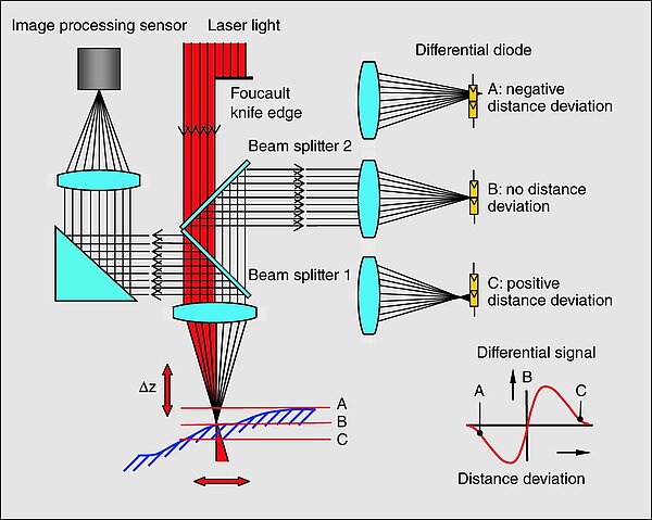
Better results can be achieved with sensors that work according to the Foucault principle (Fig. 20). Foucault laser sensors (WLP: Werth Laser Probe) utilise the aperture angle of the sensor's imaging optics as the triangulation angle. A laser beam is "cut" by a Foucault cutting edge located in the beam path and imaged onto the object at the triangulation angle determined by the lens aperture. The signal is analysed using differential photodiodes, for example. The deviations from the zero position of the laser sensor determined in this way can be used to readjust the corresponding axis of the coordinate measuring machine. The measurement result is obtained by superimposing the measured values of the laser sensor and the coordinate measuring machine. Even with this type of sensor, the material surface and surface inclination have a considerable influence on the measurement result, so that a correction of these influencing parameters is necessary. With suitable software, however, the measurement uncertainty is reduced to such an extent that it fulfils the requirements of highly accurate coordinate measuring machines.

Foucault laser sensors
<p>Fig. 20: Laser sensor based on the Foucault principle combined with an image processing sensor (illumination not shown)</p>

Laser and image processing combined

In practical use, such a Foucault laser sensor is preferably integrated into the beam path of an image processing sensor (Fig. 20). This allows switching between the two sensors without mechanical movement.

Non-contact scanning of surface profiles

In manual mode, laser scanning can also be easily observed visually. The benefit of the laser point sensor compared to the focus methods described above lies in the significantly higher measuring speed when scanning contours or surface profiles. Several hundred to a thousand points can be measured per second. Accordingly, this sensor is used to measure contours on workpiece surfaces or, for example, to check the flatness of sealing seats with a low measurement uncertainty of a few micrometres. In tool measurement technology, it is used for the measurement of rake and clearance angles or edge radii.

Capture free-form surfaces quickly

Laser line sensors (e.g. Werth LLP: Laser Line Probe) work in a similar way to the point probing triangulation sensors described above. The laser beam is set into a laterally oscillating motion by a moving mirrors integrated into the sensor head, e.g. a rotating polygon mirror or an oscillating mirror, thus generating a line (Fig. 19b, p. 26 Area sensors with pattern projection). Alternatively, this linear expansion of the laser beam can be generated using special astigmatic optics (cylindrical lens). The evaluation is carried out by a matrix camera so that a measurement result determined by triangulation is obtained for many points "simultaneously". As a result, a cross section (light section) is measured on the surface of the measuring object. To capture a three-dimensional surface, the sensor with the coordinate measuring machine is moved perpendicular to the section plane. This sensor also allows the fast measurement of larger areas with a relatively large measurement uncertainty of a few 10 µm. The application of this sensor principle is therefore focussed on housing and cover parts with surfaces that are designed primarily from an aesthetic point of view. These parts usually have relatively coarse tolerances and offer the possibility of using software filters to smooth the measurement results. The results are usually evaluated in comparison with the CAD data (see Fig. 53, p. 82 Comparison with CAD data).

Capture free-form surfaces quickly
<p>Fig. 19: Multidimensional distance sensors: a) Focus variation: Werth 3D Patch or confocal area sensor (NFP), b) Laser line sensor, c) Pattern projection sensor, d) Photogrammetry sensor</p>