learn more

Interferometric point sensors

Measure small geometries with the highest accuracy

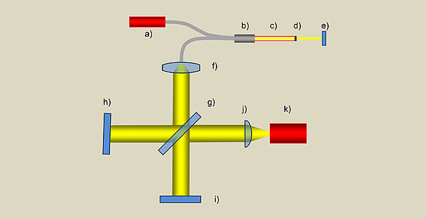
Distance sensors based on the interferometer principle measure the transit time difference between two light beams (measurement beam and reference beam), which results from the difference in length between a reference distance (distance to the reference surface) and the measurement distance (distance to the measurement object surface) (Fig. 8). The evaluation is carried out by determining the phase shift when the two beams are superimposed. By simultaneously using several slightly different frequencies (colours), the absolute value of the distance to the object surface can be measured from the resulting beat (heterodyne method).

<p>Fig. 8: Distance measurement method: a) Interferometer (time of flight): The distance to the object can be determined by interference from the transit time difference between the reference beam and the measurement beam. b) Triangulation (angle): The distance to the object can be determined from the position of the light spot in the measurement field and the known triangulation angle (sensor arrangement according to Scheimpflug to avoid blurring). c) Focus method (angle): The distance to the object is determined from the focus state, defocussing depends on the aperture angle.</p>

Absolute measurement with multiple frequencies

Fiber optic interferometers are suitable for measuring small geometries and features deep within the object. The spectrum of several light frequencies is generated by using short-coherent superluminescent diodes (SLD). This allows the absolute value of the distance to be measured. Even after an interruption in the measuring process, e.g. during positioning or due to surface defects on the workpiece, the reference point of the distance measurement is retained. This behaviour means that even optically rough surfaces can be measured.

Fiber optic probes for small details

Figure 22 shows the basic structure of the Werth Interferometer Probe (WIP). The light from the superluminescent diode is coupled into an optical fiber via a fiber optic coupler and transmitted to the actual measuring probe. The reflection at the exit surface of the probe results in a reference beam. The measuring beam is created by reflection from the workpiece surface. At technically sensible working distances, the path length difference between the two signals is too great for interference (short coherence length). Both signals are transmitted to the evaluation interferometer via the fiber coupler and another optical fiber. Here, the path length difference is compensated for by splitting the beam path and correspondingly different path lengths in the partial beam paths (adjustment of the mirror distances). The reference beam and measurement beam are superimposed and thus caused to interfere. By tilting one of the two mirrors, the axial position information of the beams (depending on the position of the workpiece surface) is converted into laterally analysable information. The different optical path lengths are compensated for simultaneously, resulting in interference for all distances within the measuring range. Depending on the position of the mirrors at which the beam is reflected, different intensities and thus interference patterns are created laterally. These are captured with a camera and the distance between the reference surface and the workpiece surface is then determined.

Fiber optic probes for small details
<p>Fig. 22: Principle of the interferometric point sensor (WIP): a) superluminescent diode, b) fiber coupler, c) probe, d) probe exit and reference surface, e) workpiece surface, f) collimator lens, g) beam splitter, h) mirror 1, tilted, i) mirror 2, j) cylindrical lens, k) line camera</p>

Rotate, tilt and change

The evaluation unit contains both the light source and the evaluation interferometer. The actual fiber optic measuring probe is attached to the coordinate measuring machine via a magnetic interface. The probes can be designed for different exit angles. Thanks to an automatic probe change and the rotatable arrangement of the probes (Fig. 23), measurements or scans can be taken in practically any orientation. Due to the very low measurement uncertainty (≤ 1 µm) and the probe geometry, the sensor can be used for geometry, form and roughness measurements in small and deep bores and slots, for example.

Rotate, tilt and change
<p>Fig. 23: Rotatable and interchangeable probe of the interferometric point sensor (WIP) and roughness measurement in injection holes of diesel injection nozzles (small partial illustration)</p>