learn more

Switching tactile sensors

Simple functional principle

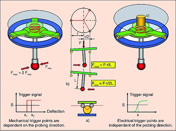
Simple touch trigger probes work according to the tripod principle (Fig. 27 left). When the stylus tip contacts the measuring object, a signal (trigger) is generated to read out the scale systems of the coordinate measuring machine. The measurement points are derived from the coordinates of the measuring machine and refer to the centre of the stylus tip. This is mounted via a rigid shaft on a three-point bearing, which is designed as a switch in each of the three supports. If the stylus is deflected from any orientation, at least one switch is opened. This is further processed as a trigger signal. The main disadvantage of this system is that the probing forces are highly dependent on the probing direction. This leads to different probe deflection and thus to a non-negligible direction-dependent probing error (triangular characteristic), which is difficult to correct.

<p>Fig. 27: Trigger probes: principle with mechanical contacts (left): circuit is interrupted when deflected (a). Due to the three-point bearing (b), the probing force and the position x of the switching points at the threshold value S are direction-dependent by a maximum factor of 2 ("lobing"). Principle with tactile-electric transducer (right): The electromechanical transducer (c) generates an almost direction-independent signal before the three-point bearing triggers.</p>

Probing behaviour independent of direction

Higher-quality touch probes use transducer elements such as piezo elements or strain gauges to convert the mechanical signal into an electrical signal (Fig. 27 right). They can be used to achieve a largely direction-independent probing behaviour. Downstream electronics ensure that it is possible to work with very low probing forces. The measurement uncertainty influenced by the sensors is lower. The tripod is usually only deflected after the probing point has been detected. This makes relatively long "braking distances" in the axes permissible. A common disadvantage of all trigger probes is that the coordinate measuring machine is brought into contact with the measuring object to determine a measuring point and then has to be moved out of contact again. This results in probing times in the range of seconds for each measurement point. The main advantages of the trigger probes over the scanning probes described below are their relatively low price and somewhat smaller dimensions. Due to the small number of measurement points, their use is limited to the measurement of features with negligible form errors (Fig. 26).

Probing behaviour independent of direction
<p>Fig. 26: Effect of the number and position of the probing points on the measurement result for an object with form error: a) real contour with form error (shown magnified); b) four probing points and the Gaussian compensation circle calculated from them; c) four further probing points with compensation circle – there are considerable deviations from the result from b); d) probing points obtained by scanning (only partially shown) and the "correct" compensation circle – due to the high number of points, it also makes sense to determine the form error here; e, f) The minimum circumscribed circle (maximum dimension) and the maximum inscribed circle (minimum dimension) are determined by extreme points and can therefore only be measured with a high point density. g) The position of the centres of the circles also varies.</p>